¶ Oil Pickup: When the Oil Pump Draws Air Instead of Oil
¶ The key points at a glance
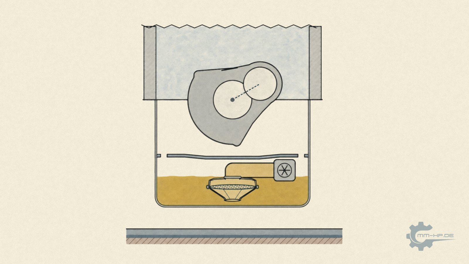
Before the oil pump can deliver anything, the oil has to reach it. It covers this first stretch through a short tube that ends at the bottom of the oil pan in a pickup bell. The bell is a flat head with a large-area screen, with a funnel below it whose opening is about the size of the tube. It hangs just above the pan floor, at the point where the oil stands deepest when the car is at rest.
This first metre is rarely noticed because it almost always works in everyday use. Yet it decides whether the pump draws oil or air. If the bell draws air, less oil reaches the engine and oil pressure falls, even though the pump, the bearings and the oil level are all fine.
Three things decide whether the bell stays in the oil. The screen must be large enough to tolerate dirt without choking the flow. The bell must sit at the right height. Too close to the floor and it throttles the flow and can pull in sludge, too high and it is the first to draw air when the level is low. And the oil must not run away from the bell during manoeuvres. When braking, pulling away, climbing and cornering, the oil surface tilts, at 45 degrees for an acceleration of one g. Where the bell sits in the pan, how the pan is shaped and whether a baffle slows the oil then decides whether the bell stays submerged.
There is therefore no single position that suits every engine. It follows from the installation orientation, the pan shape, the oil quantity and what the vehicle has to do in daily use. Racing engines sidestep the problem with a dry sump. For production vehicles, a carefully designed wet pan is the right solution.
That was the short answer. If you want to understand why an unremarkable sheet-metal bell helps decide oil pressure, the long version starts here, with animations for every driving state, the figures behind them and the relationships between pan, bell and driving state.
¶ The first metre of oil supply
A lot is written about oil pumps. How much they deliver, what pressure arrives at the end, how the pressure relief valve works. Hardly anyone asks where the pump gets its oil from. Yet this is the only point in the whole circuit where the oil is not pushed but pulled.
An oil pump is a positive displacement pump. On the pressure side it builds as much pressure as the engine opposes to it, until the pressure relief valve opens. On the suction side, however, it can only create as much vacuum as the air pressure above the oil surface allows. The oil is pushed into the bell by the atmosphere, and the pump merely creates the space for it. No more than about one bar of pressure difference is ever available on this side, and a good part of it is lost before the oil reaches the pump, in the screen, at the inlet edge, and in the length and bends of the tube.
Anything that goes wrong on the suction side cannot be made up for on the pressure side. A stronger pump does not help if the bell draws air. It then simply delivers more air.
The components of this first metre are few.
| Component | Job | What can go wrong |
|---|---|---|
| Oil pan | holds the oil reserve, collects the returning oil | oil runs away from the pickup point during manoeuvres |
| Pickup bell with screen | fixes the pickup point, holds back coarse particles | screen clogs, bell surfaces and draws air |
| Pickup tube | connects bell and pump | a leak above the oil level draws air |
| Baffle | slows the oil, separates the crankshaft from the oil reserve | missing, or too small for the application |
Anyone who understands the suction side also understands many oil pressure problems that make no sense at first glance. A pressure drop only in fast corners. A warning light that flickers briefly only on a hill. An engine that runs without problems with a full oil level and suddenly shows unsteady readings just above MIN.
¶ Pickup bell instead of a bare tube end
The simplest pickup would be a tube hanging open in the oil. On oil pumps like those fitted to TDI engines, however, the end of the tube carries a bell. The photos show what it looks like.
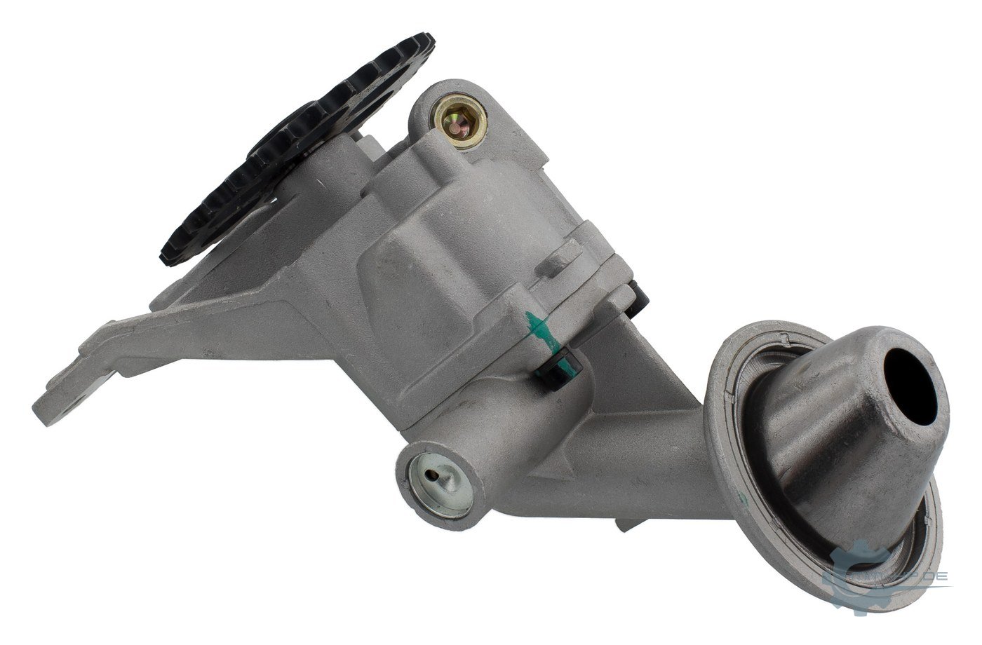
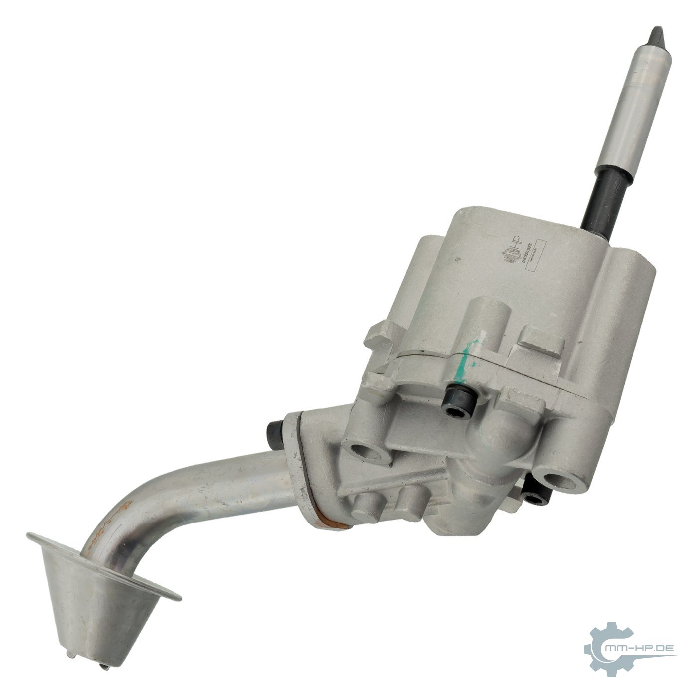
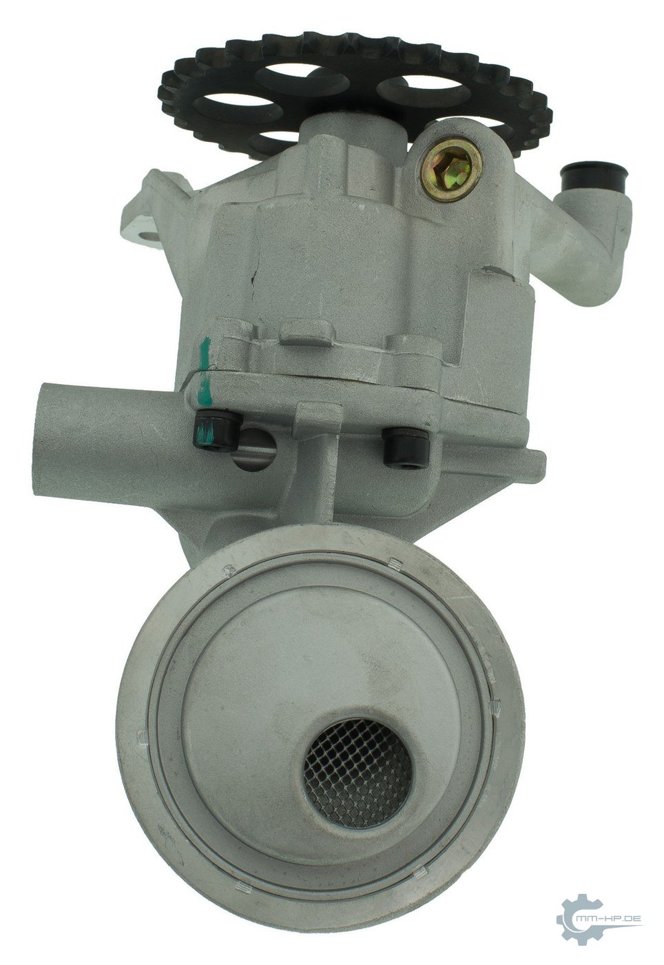
On these pumps the design follows the same pattern. At the top, where the tube arrives, sits a flat head made of sheet metal. In the joint between the head and the funnel lies a large-area wire screen. Below it the funnel narrows to an opening that roughly matches the tube cross-section. A crimped rim holds the two halves together.

This shape solves three jobs at once.
The small opening at the bottom fixes the pickup point. The oil is always drawn in at the same place, just above the pan floor, where it stands deepest when the car is at rest. A bare tube end with a large screen would instead draw over a wide area, including from higher up.
The funnel guides the oil from the pan space into the tube through a rounded transition. In fluid mechanics, a sharp-edged tube end set flush in a wall has an entrance loss coefficient of 0.5. If the tube projects freely into the oil, the value is higher still. This means that half of the velocity energy is lost as pressure loss on entry. A cleanly rounded inlet reduces this value considerably. By Swamee's approximation it is still about 0.08 at a rounding radius of one fifth of the diameter, between 0.03 and a good 0.1 depending on the calculation method. In absolute terms, at the usual flow velocities, these are only a few millibar. What matters more is that the funnel guides the oil into the tube evenly and without separation at the edge.
Finally, the flat head carries the screen, in a size that would not fit inside the tube. Why that matters is shown in the next section.
¶ The screen, and why area makes the difference
The screen in the bell is not a filter. Fine filtering is done by the oil filter on the pressure side. The screen only holds back what would damage the pump. Gasket remnants, swarf after a repair, abrasion from plastic parts and, in the extreme case, the teeth of a timing belt that runs in oil. Its mesh is therefore much coarser than that of an oil filter, so that it offers the oil as little resistance as possible.
What a screen catches stays there. The oil filter is replaced at every oil change, the screen in the bell is not. It collects over the whole life of the engine, and every particle that sticks to it covers part of the free area. The same quantity of oil has to pass through less and less free area, and the pressure loss at the screen rises.
This is the real advantage of the bell. Give an open tube and a bell the same amount of dirt, and it spreads over a small area in the tube screen and over a many times larger area in the bell. In our schematic drawing the screen area of the bell is about eleven times the tube cross-section. Each particle in the tube screen therefore covers an eleven times larger share.

The animation shows what happens then. With every particle, the vacuum behind the small screen rises. At some point the pressure is so low that the air dissolved in the oil comes out of solution. If it falls further, vapour bubbles form as well. The pump then no longer fills its chambers completely and delivers less, even though it keeps turning. Vapour bubbles collapse abruptly on the pressure side. This is cavitation, and over time it damages the pump itself. The bell with its large screen tolerates the same amount of dirt without the vacuum rising noticeably.
A clogged screen gives no warning. There is no sensor for it, and at idle, when the pump has little to deliver, the remaining area is often still enough. Pressure only collapses at high engine speed, when the pump wants to draw a lot, or at a cold start, when the oil is viscous. Anyone who changes only the oil filter on an engine with a known particle source, such as a disintegrating timing belt in the oil, leaves the screen in the engine with everything it has collected. After damage involving abrasion, the oil pan therefore has to come off, and the bell is cleaned or replaced.
¶ How high the bell sits above the floor
The opening of the bell hangs just above the pan floor. How close is one of the underrated design parameters of the whole pickup. There are two mistakes, and they lie in opposite directions.
If the bell sits too close to the floor, the oil has to flow through a narrow annular gap under the rim to reach the opening. This gap has the shape of a cylinder wall, and its area is the circumference of the opening times the distance to the floor. If it becomes smaller than the opening itself, the gap turns into a bottleneck. The oil shoots through, the vacuum rises, and sludge lying on the floor can be carried along and drawn straight in front of the screen.
If the bell sits too high, nothing is throttled. But it lacks reserve below it. If the oil level drops, for example because the engine consumes oil or the level was kept low at the change, it reaches this bell first. And it does not only draw air once the surface reaches its opening. A vortex can form above the pickup point earlier than that, with an air core reaching from the surface down to the opening. This is well studied in pump engineering. The American standard for pump intake basins, ANSI/HI 9.8, requires a minimum submergence, expressly to prevent strong air vortices from entering the pump or pipework. The Hydraulic Institute, which publishes the standard, writes: "minimum submergence is also needed to prevent strong air core vortices from entering the pump or piping". The standard applies to calm water basins, not to a sloshing oil pan. The mechanism is the same, however.

Where is the right height? A simple calculation gives the lower limit. The wall area of the gap is exactly as large as the opening when the distance is one quarter of the opening diameter. For an opening of 20 millimetres that is 5 millimetres, for 25 millimetres a good 6 millimetres. Below that, the gap becomes a bottleneck. This is our own calculation, not a manufacturer specification. Values of the same order of magnitude can be found in US forums and tuning guides for V8 engines, there given as 1/4 to 3/8 inch, or roughly 6 to 9.5 millimetres. One technical article calls 3/8 inch, in its own words, "close to ideal".
A little more distance does no harm, while considerably more costs reserve below. There is one factor that no calculation captures. A sheet-metal oil pan can be dented after a grounding, and then the bell suddenly sits much closer to the floor than it was built.
¶ The oil surface moves with the car
At rest the oil surface lies level. As soon as the vehicle accelerates, brakes, takes a corner or stands on a slope, the surface tilts. It always stands perpendicular to the effective gravity, that is, to the sum of gravitational pull and the inertial force that the oil experiences at every change of speed.
How much it tilts can be calculated directly. The angle is the arctangent of acceleration divided by gravitational acceleration. A technical article on oil pans summarises it by saying that one g of acceleration acts on the oil just "as tilting a stock oil pan at a 45-degree angle".
| Driving state (round example values) | Acceleration | Tilt of the oil surface |
|---|---|---|
| brisk pull-away | 0.4 g | 21.8° |
| hard braking | 0.5 g | 26.6° |
| corner at the grip limit of road tyres | 0.8 g | 38.7° |
| emergency stop | 1.0 g | 45.0° |
| fast corner on a race track with sports tyres | 1.2 g | 50.2° |
| Formula 1 in a corner | 3.0 g | 71.6° |
The middle values are everyday driving. In an emergency stop at around one g, the oil in the pan stands 45 degrees tilted. A gradient has a similar effect. A 20 per cent gradient corresponds to a good 11 degrees, and that adds to the tilt from acceleration when pulling away on a hill.
Then there is the sloshing. The oil does not adjust to the new tilt at once. It runs over, swings back and only settles after a few oscillations. At the moment of overshoot, the surface briefly stands even steeper than the calculation says.
¶ Bell position at the front, in the middle or at the rear
The bell hangs at a fixed point. When the oil moves, it can run away from it. Whether that happens depends on where in the pan the bell sits. The following animation shows the same oil pan with the same oil quantity and the same driving programme, once with the bell at the front, once in the middle and once at the rear.

No position is best in every driving state. Pulling away and driving uphill push the oil to the rear, braking and driving downhill push it to the front. A bell at the rear in the sump stays in the oil when pulling away and surfaces when braking. In this pan with a step, by contrast, the front position stays under oil in all driving states, because the sump catches the oil when braking. That is the result for this one pan shape. With a different step, a different sump or a different oil quantity, the good position shifts.
A time lag often causes confusion here. Oil pressure does not fall at the moment the bell surfaces. The air first has to travel through the tube and the pump into the circuit. Conversely, pressure does not rise again at once when the bell is submerged again. A briefly flickering oil pressure warning light after an emergency stop or at the end of a long descent can therefore have to do with the pickup.
¶ Longitudinal or transverse, the same pan on a different axis
An oil pan is almost always long along the crankshaft and narrow across it. How far the oil travels in a manoeuvre depends on which direction the long side points. And that is decided by the installation orientation of the engine.
With a longitudinally installed engine, as in the Audi A4 or A6, the long side points in the direction of travel. When braking and pulling away, the oil covers the long distance. In a corner it moves across the short side. With a transversely installed engine, as in the Golf, Passat, Tiguan or the T5 and T6, it is the other way round. Here the corner is the critical case.

The plan view shows an effect that cannot be seen at the surface. The bell can draw air even though it still stands in the middle of the oil. What matters is not whether there is oil above it, but how much. If the layer above the opening becomes too thin, the same vortex can form as with a bell that sits too high. The light area in the schematic pan marks the zone in which the oil stands too shallow for this. The bell therefore does not surface only when the floor runs dry. It starts to draw air well before that.
Whether longitudinal or transverse, every installation orientation therefore needs its own sump and bell position. A pan that works well in a transverse engine cannot simply be transferred to a longitudinal engine, even if the engine above it is the same.
¶ Baffles, keeping the oil down
If the oil moves during manoeuvres, the idea of putting something in its way suggests itself. That is what the baffle does. In production engines it sits as a barrier between the crankshaft and the oil reserve, just below the path traced by the crankshaft counterweights and above the oil level.
Volkswagen calls this part Schwallsperre in its parts catalogue. For the Golf 2.0 TDI Common Rail, for example, the catalogue lists 03L 103 623, and for the EA288 04L 103 623 E or F. It is not always a flat plate. According to dealer information, the Schwallsperre 03L 103 623 A is a moulded part made of glass-fibre-reinforced plastic. For the 2.0 TDI with balancer shaft module, the parts catalogue lists no separate Schwallsperre in the pan. There the module itself sits below the crankshaft.

The animation shows the two jobs that are documented in patents from several manufacturers.
The first is the pickup. When braking, the oil runs forward and tries to climb the wall. Without a baffle it can, and in the middle, where the bell sits, too little remains. With a baffle, the oil hits it from below and is capped. It cannot escape further upwards, so more of it stays down and the bell stays covered. Mazda names as a goal in one patent that the screen inlet does not surface from the oil. General Motors, in another, wants enough oil at the pickup point even with sudden braking or acceleration.
The second job is the separation of crankshaft and oil. The crankshaft constantly flings off oil that emerges from the bearings. Without a baffle it falls directly onto the oil surface, and the airflow of the rotating shaft sweeps across the surface. With a baffle, the flung-off oil falls onto the plate and runs back in a controlled way through slots. Oil that hits the rotating shaft also costs power. This effect grows with engine speed.
Both have a limit, and the animation shows it. The baffle is not a sealed lid. Through the slots, some oil is also pushed upwards when braking and then runs back. The baffle slows the oil, it does not lock it in. How much it slows it depends on shape, position and slot pattern.
Two things are often read about baffles, and neither is proven. The first is the claim that they prevent foam in the oil. A series of measurements at the Massachusetts Institute of Technology found no influence of the baffle design on the air content at the pump inlet on a V6 engine, and a second on the same engine found even less foam without a baffle. A simulation by Chrysler, by contrast, sees an influence. The second is power gains in horsepower. Such figures come mostly from accessory advertising and forums. We found no reliable measurement for production diesels.
¶ Flaps and chambers come from motorsport
In motorsport and the accessory trade you find a more elaborate solution, a chamber around the pickup bell whose walls are fitted with one-way flaps. Oil can get in but can hardly get out again. Such pans keep a reserve at the bell even in long fast corners.
These flaps are not common in production engines. All the examples we found are retrofit solutions for engines that reach their limits on the race track. Series production works with fixed plates, plastic inserts and vertical walls with passages at the bottom. A Daimler-Benz patent from 1973, for example, describes a pan with three chambers, whose central suction chamber is connected to the outer ones through narrow passages.
¶ No bell position suits every engine
Where the bell sits correctly depends on the engine, and on more parameters than you might first suspect.
| Influencing factor | Why it matters |
|---|---|
| Installation orientation | decides whether braking or cornering pushes the oil across the long side of the pan |
| Pan shape | step, sump, wall slope and the space around subframe and gearbox determine where the oil goes |
| Oil quantity between MIN and MAX | determines how much reserve stands above the bell when the level is at the lower end |
| Bell size and distance to the floor | determine throttling, screen reserve and the depth at which the vortex sets in |
| Pump delivery rate | the more it draws, the faster the oil flows into the bell and the earlier it draws air |
| Return flow | how quickly oil returns from the head and crankcase decides the level while driving |
| Baffles and internals | slow the movement, each shape differently |
| Use of the vehicle | city traffic, motorway, trailer on a hill, off-road or race track demand different reserves |
Many of these parameters influence each other. A pump with higher delivery rate draws faster and therefore needs more submergence above the bell. A lower bell gives more reserve below but reduces the gap to the floor. A baffle helps when braking but can slow the return flow if it is badly placed.
In addition, the oil level while driving never matches the level that the dipstick or display shows at rest. Part of the oil is always on its way through the top of the engine, in the bearings, in the cylinder head, in the return channels. How much depends on engine speed, oil temperature and engine design. A bell that is generously covered at rest has less reserve in operation than the measurement at rest promises.
Anyone who changes a pickup therefore always changes a whole system. A different pump, a different suction pipe or a different bell height can help in one driving state and harm in another. A change to the pickup therefore has to hold up in all driving states, not just at idle.
How we design bell position, tube routing and screen area for a particular engine, we keep to ourselves. This design has grown over many years on real engines and is part of what makes our work, just as every manufacturer protects its know-how.
¶ The dry sump in the racing engine
The dry sump solves the problem of the wandering bell in a fundamentally different way. It is widespread in motorsport and fitted to some high-performance production vehicles.
With a dry sump there is no oil reserve in the pan. The pan is flat and stays almost empty. Several scavenge stages of the oil pump draw the returning oil from the lowest points, together with the air it brings with it, and deliver it to a separate tank. This tank is built tall and narrow, with internals against sloshing, and the oil has time there to release the entrained air. A separate pressure stage draws from the very bottom of the tank and supplies the engine.

Schematic. The long fast corner at 1.2 g is an assumption for the illustration, not the limit of any particular engine.
The advantage lies in the geometry of the tank. Because it is narrow, the oil surface moves only a little even under strong lateral acceleration, and the outlet at the very bottom stays under oil. In Formula 1 this withstands lateral forces of up to three g, at which a wet sump would starve. The pumps there are multi-stage, with a pressure stage and one or more scavenge stages that deliver oil and air together.
A second advantage is often overlooked. Without a deep sump the engine sits lower in the vehicle. Mercedes-AMG states for the AMG GT engine that its already low installation position could be lowered by a further 55 millimetres thanks to the dry sump. The centre of gravity drops, and the vehicle handles better.
The price is high. A dry sump needs several pump stages, a tank, additional lines and more oil. It costs space, weight and money, and on some dry sump engines, such as the Corvette Z06, the oil level measurement is only correct with a warm engine and after a fixed waiting time. For an everyday diesel that is driven far below the grip limit of its tyres, this effort is out of proportion to the benefit. Here a well-designed wet pan with a suitable bell position and Schwallsperre is the right solution.
¶ Oil level, warning light and screen in everyday use
The oil level is more than a maintenance figure. It is the reserve above the bell. Anyone who drives with the level just above MIN drives with the smallest reserve the manufacturer has provided for, and that is exactly where the driving states start to become critical that play no role with a full level. This applies especially to engines that consume oil. Too much oil is not a solution either, because the crankshaft can then dip into the oil, as we described in the article on blow-by and oil mist.
If the oil pressure warning lights up only briefly after an emergency stop, in fast corners or on a hill, the pickup can be the cause. The first step is the oil level. If the warning stays on or also appears during calm driving, the engine must be switched off and the cause sought, the pump included.
After damage involving abrasion, such as a disintegrated timing belt or chain parts, the oil pan has to come off. The screen in the bell collects over the life of the engine, and an oil change does not reach it.
A dented oil pan after a grounding is more than a cosmetic flaw. It can have brought the bell closer to the floor than it was built.
And with every change to the pump, suction pipe or pan, the pickup remains a system. What works at idle also has to work when braking, on a hill and in a corner.
¶ See also
- Understanding the oil pump: what it does, where its limits lie, and what it fears
- Timing belt in oil: the time bomb you can't inspect
- The balancer shaft module in the 2.0 TDI (EA189): design, weak point, consequences
- The Oil-Pressure Warning Light: What It Really Tells You, and What It Doesn't
- Why More Delivery Rate Is Always the Better Choice
Transparency note: MMHP has been developing, testing and manufacturing its own products for the automotive industry for over 25 years, including solutions for the oil supply of VW TDI engines. The relationships in this article rest on fluid mechanics, standards, manufacturers' patents and technical articles, and the sources are given at the relevant sentence. The animations are schematic, and their dimensions are not taken from any particular engine.