¶ Understanding the Oil Pump: Function, Limits, Weak Points
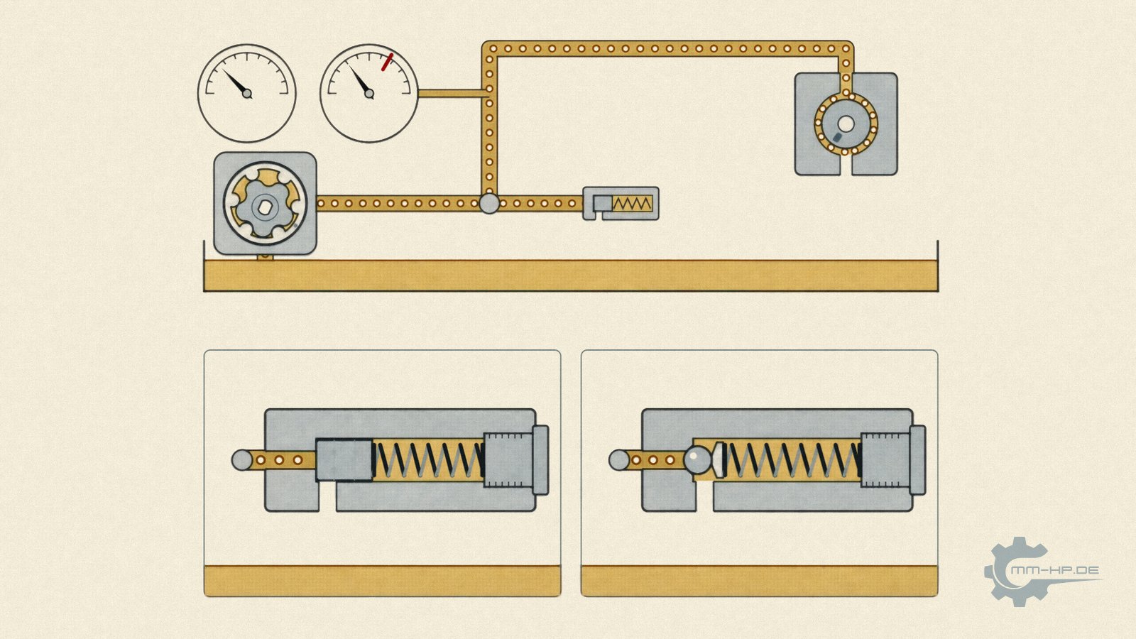
Schematic. The animation is further down in this article.
¶ The key points at a glance
The oil pump is a positive-displacement pump: it delivers a fixed volume of oil per revolution, and its delivery rate rises and falls linearly with engine speed. It does not generate pressure — it generates a flow. Pressure only arises because that flow runs up against the engine's narrow bearing clearances and passages. That's why the same pump produces two completely different pressure curves in two different engines, and why hot idle is its weak point: low engine speed, thin hot oil, and wear-widened clearances all coincide there. The standard pump in the 2.0 TDI can drop to 0.4–0.5 bar at that operating point.
At the top end, the pressure relief valve (PRV) — a spring-loaded piston that routes excess oil straight back to the sump — keeps watch. It works in every production engine, at every cold start, purely mechanically, and it has proven itself millions of times over. Too much oil pressure is therefore ruled out by design; too little, on the other hand, is a real everyday scenario.
What an oil pump truly fears is a third factor: hard particles. Its gear-tooth clearances measure only a few hundredths of a millimetre, and it is the only highly loaded component in the circuit that sits ahead of the oil filter. Between it and any dirt in the sump stands only a coarse-mesh suction strainer.
So much for the short version. The long version explains exactly how the pump in the 2.0 TDI is built, why its delivery curve is weak at the wrong end, what the pressure relief valve looks like from the inside, what modern demand-regulated pumps have made of the same principle, and why "too much pressure" is the wrong worry while particles would be the right one.
¶ A component nobody notices until it's too late
No component in the engine works as invisibly as the oil pump. It has no dashboard display, no service interval, no mention in the logbook. As long as it does its job, it simply doesn't exist for the driver. Yet literally every rotating part of the engine depends on it: crankshaft and connecting-rod bearings never run on bare metal in operation, but on a wafer-thin oil film that only holds up as long as oil keeps being supplied. If that supply stops, the film collapses and metal touches metal at relative speeds of several metres per second. From that point, the damage clock runs in seconds, not kilometres.
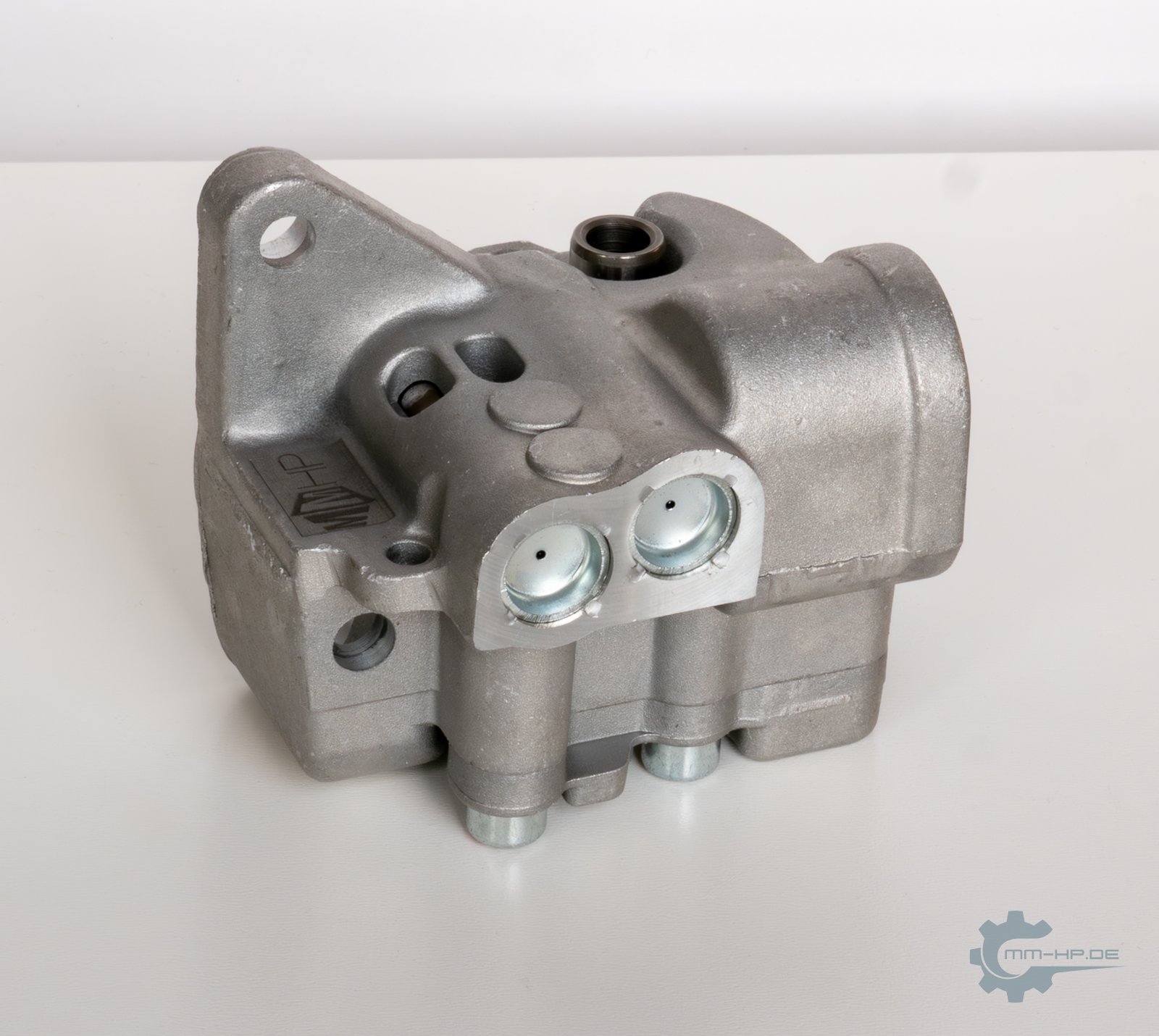
New part, own photo. An oil pump from the 2.0 TDI: small, inconspicuous and fitted deep down in the engine.
To understand why we place so much weight on the pump in our conversion kits, it's worth taking a thorough look at this invisible component. Not as a crash course for the workshop, but as a foundation for understanding: what exactly does an oil pump do, where do its design limits lie, and what actually needs protecting against?
¶ The displacement principle: the pump knows only volume, not pressure
All engine oil pumps work on the same basic principle: positive displacement. Rotating chambers pick up oil on the suction side, carry it along the housing, and release it again on the delivery side. Per revolution, an almost constant volume is moved. The delivery rate follows a wonderfully simple relationship: volume per revolution times engine speed. Double the speed means double the delivery rate, half the speed means half the delivery rate — a dead-straight line.

Schematic, not to scale. The chambers between the rotors grow over the suction port and draw in oil, then shrink over the pressure port and push it out. Each revolution delivers a fixed volume.
At this point, let's clear up the most persistent misunderstanding: the pump does not generate pressure. It generates a flow. Pressure only arises as a consequence — because that flow runs up against a resistance: the narrow bearing clearances, the cross-sections of the oil passages, the piston-cooling spray jets. The tighter the clearances and the more viscous the oil, the higher the pressure for a given delivery rate. The wider the clearances and the thinner the oil, the lower it is. The engine determines the pressure; the pump only supplies the quantity. Anyone who takes this one sentence to heart understands almost everything written in our knowledge base about measurement position, bar-value promises, and engine-to-engine differences.
For the same reason, when support occasionally asks for the delivery rate "in litres per hour," we deliberately don't answer with a catalogue figure. A litre value only ever applies to one specific engine speed, one specific oil temperature, and one specific back-pressure — without those three figures it would be worthless, and with them, unwieldy. The percentage figure for our stages, by contrast, describes the ratio to the standard pump across the entire speed range, because both curves are linear and the ratio stays constant. It's the more honest and more robust number. We also treat the exact displacement volumes of our pump stages as part of our trade secrets, and we ask for your understanding on that.
¶ Designs: gears, rotors, and vanes
Positive displacement doesn't mean all pumps look alike. Three designs have become established in engine building, each with its own character.
| Design | Construction | Strengths | Weaknesses |
|---|---|---|---|
| External gear pump | two equal-sized, externally toothed gears | robust, insensitive to viscous oil, simple construction | pulsating delivery, audible |
| Internal gear pump (gerotor/duocentric) | externally toothed inner rotor runs eccentrically inside an internally toothed outer ring | quiet, low pulsation, high efficiency, compact | more sensitive to contamination than external gear |
| Vane pump | rotor with radially movable vanes, eccentric in the housing | very smooth delivery, can be made variable | least tolerant of viscous cold oil |
The table reads like a technical rundown, but the interesting part sits between the lines. The external gear pump is the workhorse of classic engine building — it forgives almost anything and, if necessary, will still deliver honey-thick oil. The internal gear pump, often called a gerotor after its operating principle or "Duocentric" after a widespread design, has largely replaced it in modern passenger-car engines because it's more compact, quieter, and more efficient. The vane pump, finally, is the basis for most variable, "demand-regulated" oil pumps, which we'll come to further below.

Schematic, animated. In all three designs a chamber is filled on the suction side and emptied on the pressure side, a fixed volume per revolution.
The 2.0 TDI of the EA189 generation uses a Duocentric internal-gear pump, and it sits in a location that turned out to be decisive for this engine's entire damage history: inside the balancer shaft module beneath the crankshaft, driven by one of the balancer shafts. Space there is tight, and the pump was sized accordingly tightly. On top of that comes the multi-link drivetrain with the notorious hexagon drive dog as its last and weakest link, whose wear gradually disconnects the pump from its drive. We've covered this design history in detail in our article on the balancer shaft module. For our purposes here, it's enough to know: the standard pump in this engine is not a generously sized component with reserves, but a compromise subordinated to the available space. That's the backdrop against which everything else in this article should be read.
¶ The delivery curve: strong where it's easy, weak where it counts
Plot delivery rate against engine speed and you get the straight line mentioned above. But the engine doesn't need a straight line. Its oil demand depends on load, temperature, and engine speed, and the critical combination isn't the one you'd intuitively expect.
At high engine speed, the pump delivers in abundance — far more than the engine could ever use. That's the unproblematic part of the curve. The problematic part lies at the other end, at hot idle, where three effects work against pressure at the same time:
First, engine speed. At idle, the engine turns at a fraction of its rated speed, and delivery rate falls linearly with it. By design, the pump delivers its minimum there.
Second, viscosity. Hot oil is thin and escapes through every bearing clearance many times more readily than cold oil. The resistance the pump works against collapses, and pressure collapses with it. What builds pressure almost instantly during a cold start drains away like water once hot.
Third, wear. Every bearing that has done service has larger clearances than on day one. Larger clearances act like additional drains opened up in the system. An engine with 250,000 kilometres on the clock noticeably loses more oil through its bearings at hot idle than the same engine when new, with an identical pump and identical oil.
All three effects add up at exactly one operating point: hot engine, idle speed. The queue on the motorway off-ramp after a brisk drive on a summer's day is the hardest moment of the day for the oil circuit — not the full-load driving beforehand.
So how much pressure "should" there be at hot idle? An honest answer needs two levels. The general one: workshop and forum experience across many engine families puts warm idle roughly in the range of one to three bar, with considerable spread depending on design, oil, and wear condition, and individual manufacturers specify minimum values for their engines well below that. A binding, publicly documented VW target-curve datasheet for the 2.0 TDI, on the other hand, doesn't exist — the factory maps are part of internal application documents. The specific level is our own measurement practice, and it's unambiguous: on standard 2.0 TDI pumps, we regularly see values around 0.4 to 0.5 bar at hot idle — at the lower edge of what the general experience ranges allow for at all. For context: from our point of view, idle values in the direction of 2 bar would be desirable. The entire justification for our products lies between these two figures, and anyone wanting to know how we derive the choice between our two pump stages from this will find the full reasoning in the article Why more delivery rate is always the better choice.
Key takeaway: An oil pump is always weakest exactly where the engine needs it most: with hot oil and low engine speed. Its design isn't decided at the top of the curve, but at its lower end.
¶ The silent guardian: the pressure relief valve
If delivery rate rises linearly with engine speed, but the engine can't absorb nearly that much oil at high speed, where does the surplus go? The answer is a component that's practically absent from public discussion, even though it sits in every engine and carries responsibility there non-stop: the pressure relief valve (PRV).
Its construction is disarmingly simple. A piston, a spring behind it, oil pressure in front of it. The spring pushes the piston onto its seat, keeping a return passage to the sump closed. If pressure rises above the spring's preload force, it pushes the piston back, the passage opens, and the surplus flows directly and pressure-free back into the sump. As pressure falls, the spring closes the valve again. No sensor, no control unit, no software. The control loop consists of a piece of steel and a coil spring, and it reacts the instant pressure arises. Some designs additionally guide the piston over a small oil cushion that dampens pressure oscillations and keeps the valve working smoothly.
The manufacturer sets the opening pressure via the spring. Typical workshop figures for passenger-car engines are in the region of roughly 4.5 to 6 bar, though these numbers vary considerably by engine and are given here only as an order of magnitude. What matters isn't the exact figure but the principle: above this threshold, nothing more gets through to the engine, no matter how much the pump delivers. The valve is the system's built-in lid.
This valve shouldn't be confused with a second, much smaller valve in the oil circuit: the bypass valve on the oil filter. That one opens at much smaller differential pressures and has a completely different job: it ensures the engine stays supplied even with a clogged filter or thick cold oil. Why it does that, what it says about filtration in everyday use, and why this unassuming valve becomes a serious matter in combination with timing-belt debris is covered in a dedicated article: Timing belt in oil.

Schematic, not to scale. Two designs with the same job: the pump delivers volume; pressure builds at the resistance in the engine. At the opening pressure, the pressure pushes the piston or ball against the spring, surplus oil flows back to the oil pan without pressure, and the pressure barely rises any more.
¶ Aside: what demand-regulated oil pumps reveal about the principle
Modern engines take the idea behind the pressure relief valve one step further. Instead of blowing off the surplus through a spring valve, they adjust the pump itself: flow-regulated oil pumps, in production across the VW Group since the early 2010s, adapt their delivery volume to actual demand via variable geometry or a map-controlled regulating valve. The control unit compares measured oil pressure against a stored target value derived from engine speed, load, and temperature, and adjusts accordingly. The purpose is simply fuel economy, because pumping oil against a pressure relief valve costs drive power.
For our topic, one thing about this aside is particularly interesting: it shows that "the pump delivers more than the engine needs, and the surplus gets regulated away" is not a special case — it's been the basic principle of every oil supply for decades. The question is never whether excess delivery capacity gets throttled back. The question is only how elegantly. The simple spring piston has done it robustly and maintenance-free for over a hundred years; map-based regulation does it more economically. Both paths lead to the same result: the engine never gets more pressure than the design allows.
An honest footnote belongs here too, because "more economical" has a price that's rarely spoken aloud: map-based regulation optimises for fuel consumption, not for service life. It deliberately lowers oil pressure in certain operating states — the pump could deliver more, but is electronically held back. Exactly these electronically actuated regulating valves also sit on the belt-driven oil pumps of the later EA189 variants and the EA288, and our research and testing work on these engines has led us to a clear position: for engine longevity, full, unthrottled delivery is the better choice. Our conversion solutions for these engines therefore eliminate the reduction logic entirely — there, the pump always delivers its maximum output, capped only by the mechanical pressure relief valve. The trade-off is real, and you have to choose: a few drops of fuel, or a few tenths of a bar in the critical moments. We've made our choice.
And this is where the circle closes back to everyday driving: at every cold start in winter, the oil is so thick that even idle delivery rate reaches the threshold. The pressure relief valve on your standard engine, then, doesn't work in theory — it works regularly, every winter, often for minutes at a time, with the original pump. The state "valve is continuously regulating down" is millions-of-times-proven, everyday production reality. Why exactly this winter proof also dissolves the last worry about a stronger pump is something we've worked through in detail in the delivery rate article.
¶ What the pump really fears: particles
After all this reassurance about the top end, now to the threat that genuinely doesn't get talked about enough. An oil pump practically never dies from "too much pressure." It dies from two things: a dying drive — in the EA189, the well-known hexagon drive dog — or from what it draws in.
To understand how sensitive a pump is to contamination, you have to look at its internal dimensions. The following figures come from workshop and repair literature covering various engines and should be read as typical orders of magnitude, not as values for one specific model:
| Clearance | typical new condition | typical wear limit |
|---|---|---|
| Gear-tooth backlash | from approx. 0.03 to 0.05 mm | approx. 0.08 to 0.20 mm |
| Gear-to-housing clearance | max. approx. 0.18 mm | |
| Axial clearance, gear to cover | approx. 0.10 to 0.15 mm |
Read this table against everyday scales for a moment: a human hair measures roughly 0.05 to 0.07 millimetres. The working clearances of an oil pump, then, are on the order of a hair's width, and in places well below it, in the range of a few hundredths of a millimetre. This tightness isn't a design flaw — it's the operating condition: the smaller the clearance, the less oil leaks internally back from the pressure side to the suction side, and the better the pump's efficiency.
But this very tightness is what makes the pump vulnerable. Wear research has established that the most dangerous particles are those whose size roughly matches the clearance: they fit just snugly enough into the gap, jam there, and act like a cutting tool between the surfaces. The figures from industrial lubrication engineering are drastic: gear pairs achieve a service life several times longer with clean oil than with contaminated oil — in documented cases, by a factor of 6.5. Every hard particle that travels through the pump leaves, at worst, a score mark, and every score mark increases internal leakage. The pump then genuinely delivers less at the same engine speed — a gradual, externally invisible loss of performance.

Schematic, greatly enlarged. The dangerous particle is the one that just fits the gap: it jams and cuts a score, and every score lets more oil leak back to the suction side.
And now comes the sentence that will be new to many readers: the oil pump sits ahead of the oil filter. The sequence in the circuit is sump, suction strainer, pump, and only after that, on the delivery side, the fine filter. This is structurally unavoidable, because the pump has to push the oil through the filter in the first place. But it means: the only thing standing between the dirt in the sump and the pump's hundredth-of-a-millimetre clearances is a coarse-mesh metal strainer that only holds back the biggest chunks. Everything finer travels straight through the engine's most sensitive delivery component before it has ever seen a filter. Where such particles come from, why decomposing timing belts running in an oil bath are the most insidious source, and what happens when the strainer itself clogs, is covered in the article Timing belt in oil. Fragments of a broken timing chain guide or tensioner rail can reach the intake strainer the same way, as described in our article on timing chain guide and tensioner rails.
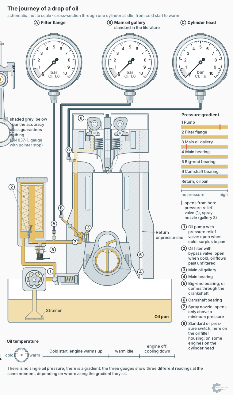
Preview from the article on measurement position: bottom left, the pump (1) draws from the pan through the strainer; only after it, above on the left, comes the oil filter (2).
➜ The journey of a drop of oil, station by station
Key takeaway: The real threat to an oil pump isn't pressure, it's dirt. It works with clearances measured in hundredths of a millimetre and, by design, receives its oil unfiltered.
¶ The second weak point: the suction side
Besides particles, there's a second enemy that's also barely ever discussed publicly, and it sits exactly where you'd least expect it: not on the delivery side, but in the pump's suction path.
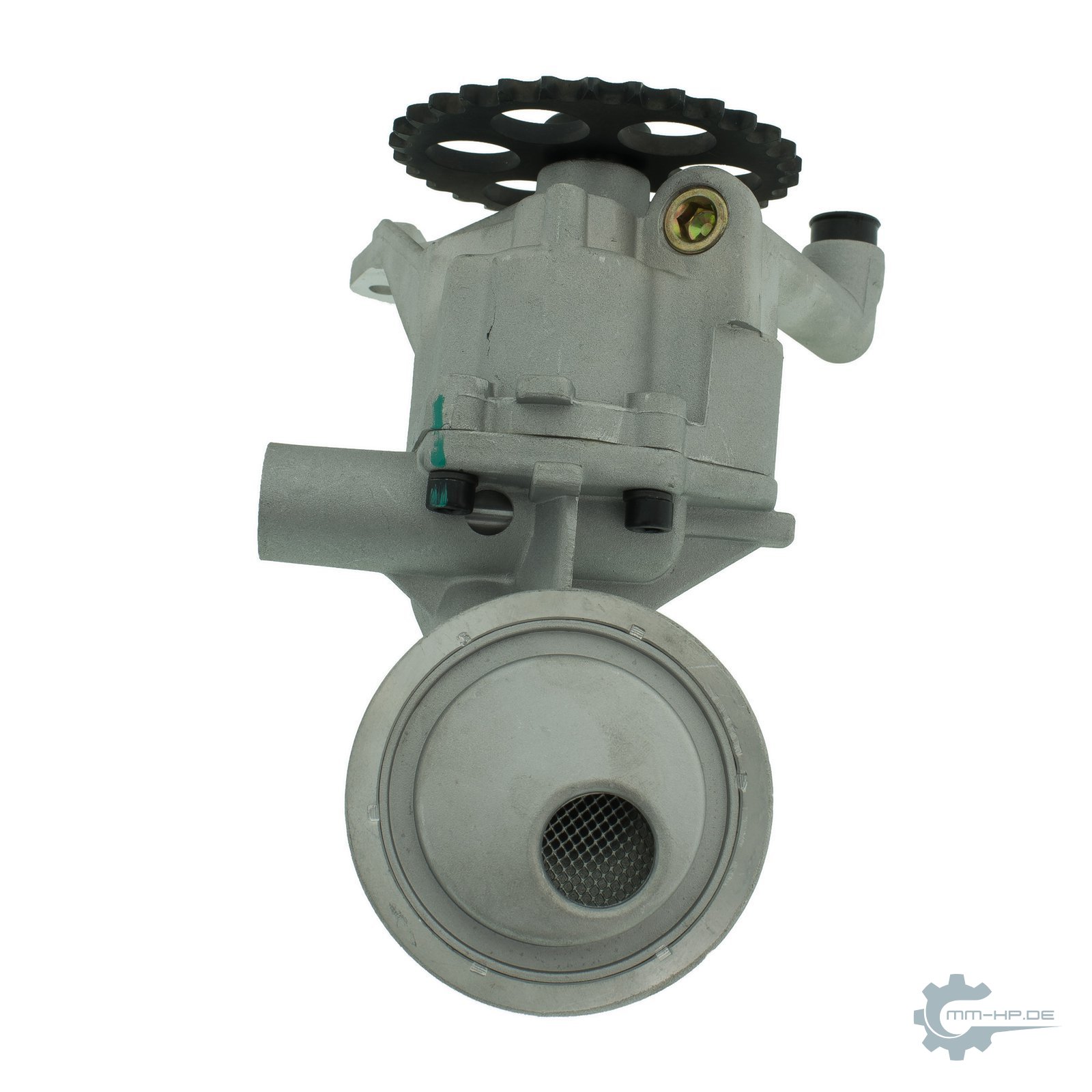
New part, own photo. At the bottom, the pickup with its strainer: this is where the pump draws oil from the sump.
A positive-displacement pump can push hard, but it can only pull weakly. On the suction side, it has only the difference between ambient pressure in the crankcase and the vacuum in its opening chambers available to it — less than one bar, no matter how strong the pump is. As long as the strainer and suction path are clear, that's entirely sufficient. But if the inflow is throttled — by a clogging strainer, a leaking suction pipe drawing false air, or simply honey-thick oil in extreme cold — the incoming oil can no longer keep pace with the speed of the delivery chambers. A vacuum forms in the chambers, and past a certain point, the oil there genuinely starts to boil: vapour and air bubbles form. Engineers call this cavitation.
Cavitation is doubly vicious. In the short term, delivery collapses, because a pump delivering bubbles delivers correspondingly less oil, pressure in the system falls, often accompanied by an audibly hoarse, rattling pump noise. In the long term, the bubbles destroy the pump itself: they collapse abruptly on the delivery side, and each of these micro-implosions hammers tiny craters into the surfaces of the delivery mechanism — material erosion under continuous operation. An engine can therefore have an impeccable pump, clean oil, and intact bearings, and still suffer from a lack of oil pressure, purely because there's an obstruction on the suction side. This exact mechanism is behind the strainer-blockage damage we describe in the timing belt article, and it belongs in every serious oil-pressure diagnosis: anyone who only looks on the delivery side is overlooking half the suspects.
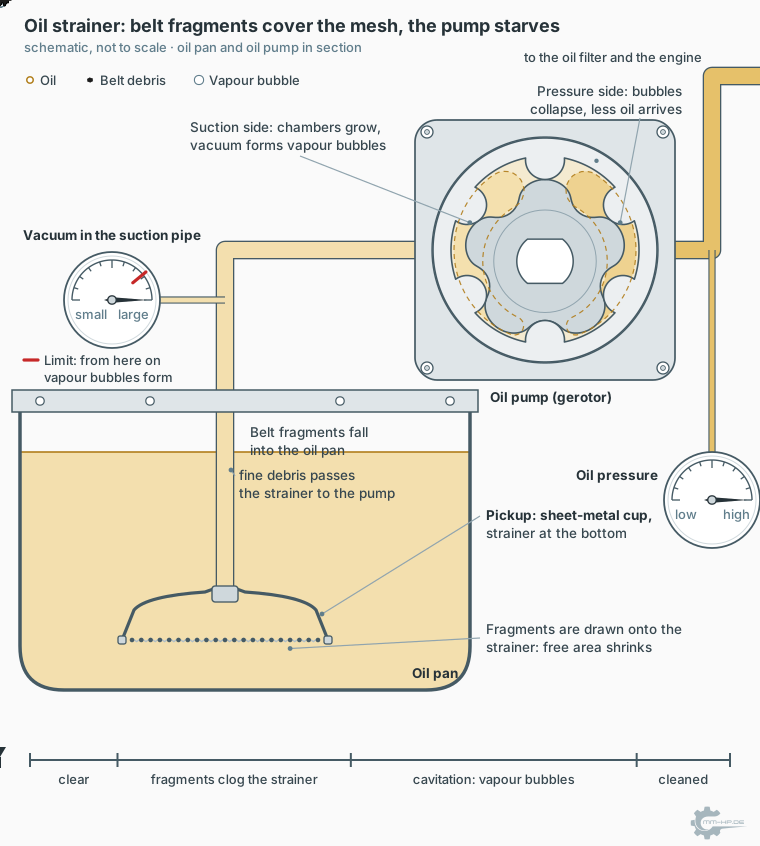
Preview from the article on timing belts in oil: this is what cavitation looks like when the strainer clogs.
How the pickup bell, the screen, the bell height and the shape of the oil pan decide whether the pump gets oil rather than air in the first place is explained in Oil pan and pickup tube: the underrated first metre of oil supply.
¶ Three ways to drive an oil pump
A pump is only ever as reliable as its drive, and the engine world has produced three concepts for this, which run through our articles like a common thread.
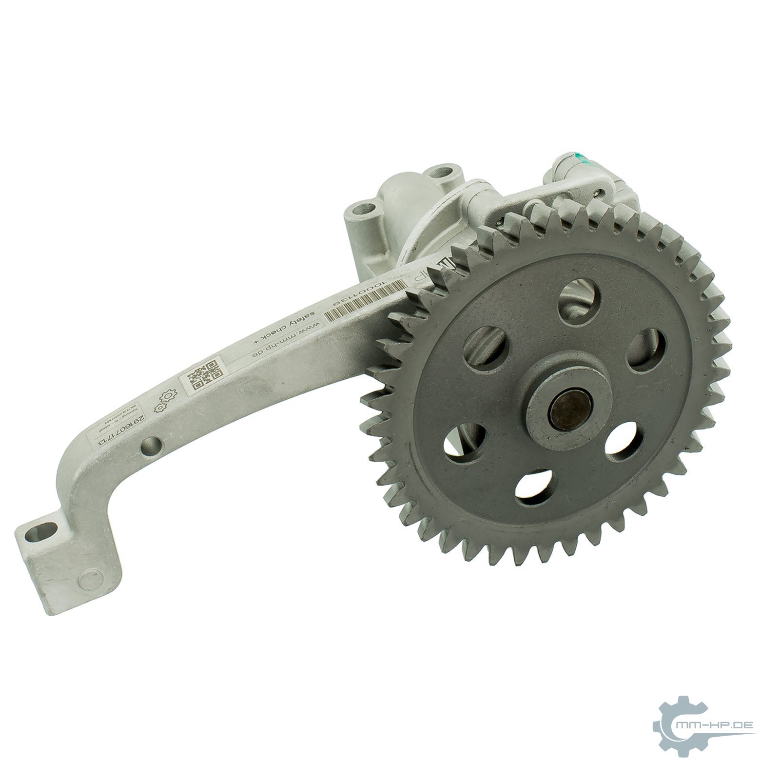
New part, own photo. Chain drive: the pump carries its own sprocket and is driven from the crankshaft by a chain.
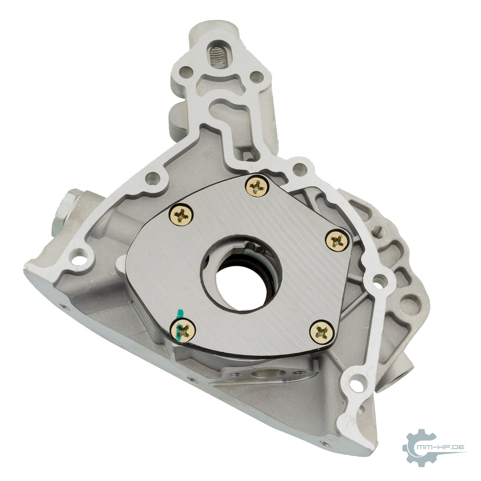
New part, own photo. Direct drive: this pump sits in the front cover; the crankshaft passes through the central bore and drives the inner rotor.
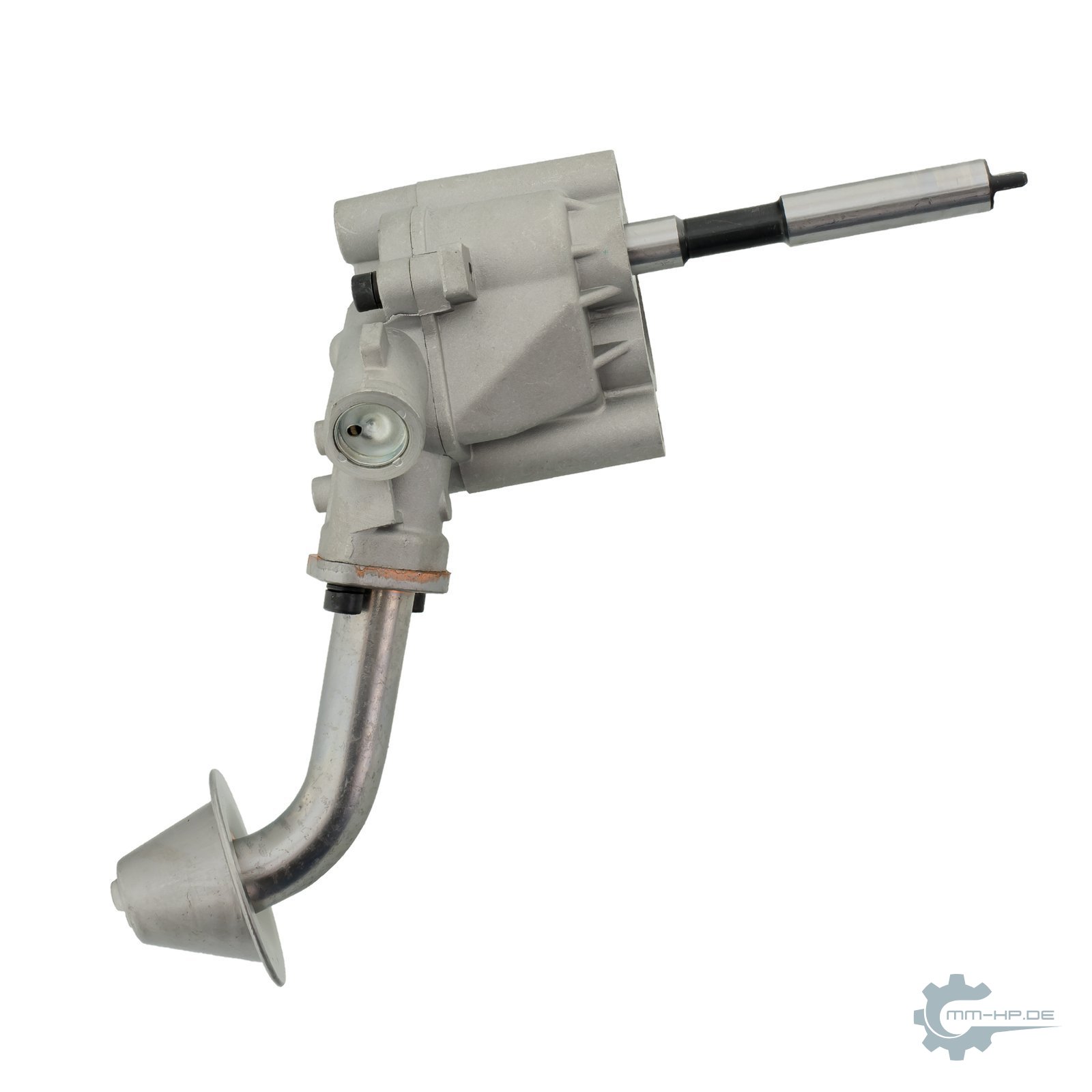
New part, own photo. Shaft drive: a drive shaft turns the pump from above, and the pickup pipe is attached directly to it.
| Drive concept | Principle | Typical weak point |
|---|---|---|
| Positive-locking drive dog | short hexagon or multi-tooth pin transmits torque | wear of the positive-locking pairing, gradual and invisible |
| Chain | roller or toothed chain, continuously lubricated | elongation and loss of tension, progressive without a tensioner |
| Timing belt in oil | belt runs directly in the engine oil | chemical degradation from ageing oil |
The EA189 with balancer shaft module connects several transmission links in series — a multi-stage gear train through the module plus the hexagon drive dog — and with this drive dog has created what is probably the best-known drive weak point in modern diesel history; its anatomy fills an entire article of its own. The EA288 generation and the 1.6 TDI use the oil-bath belt, whose pitfalls we've dissected here. And our own chain conversion uses a tensioned chain — why a tensioner is needed is explained here.
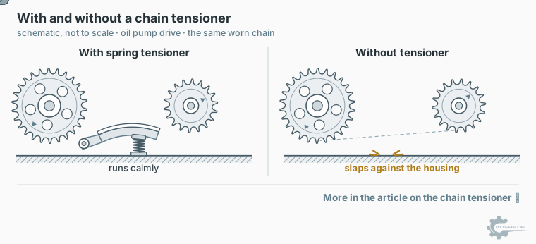
Preview from the article on the chain tensioner: the same elongated chain, once with and once without a tensioner.
➜ Why a chain drive without a tensioner destroys itself
The lesson from this small systematic overview is the same as throughout the article: the oil pump itself is almost never the problem. Its surroundings are — the drive ahead of it, the strainer beneath it, the particles inside it. Anyone seriously wanting to improve an engine's oil supply has to think in terms of the system, not the individual part, and that's exactly the design approach behind our conversions.
¶ The safety margins, in numbers
Back to the reassuring side, because it can be quantified. We regularly get questions like: can the plastic housing of the oil filter withstand the stronger pump? Does the engine electronics flag a fault if oil pressure rises?
For the first question, it's worth looking at the filter industry's testing practice. Automotive oil filters are tested to the ISO 4548 standard series, among other things with sustained pressure pulses between 0.2 and 35 bar and burst tests up to 100 bar. As a reminder: operation takes place at a few bar, capped by the pressure relief valve. Between operating pressure and tested burst strength, then, there's roughly a factor in the double digits. These figures describe standard industry testing practice, not a specific VW datasheet, but they show the design philosophy of the entire supplier industry: oil-circuit components are built with margins that exceed everyday operation by orders of magnitude. Our own assessment after years with these engines matches this: the components withstand many times what the pump could ever deliver, and thanks to the pressure relief valve, that multiple never reaches them in the first place.
On the second question: the 2.0 TDI's oil-pressure monitoring is an under-pressure warning. It triggers when pressure falls below the stored threshold, because a shortfall is the real danger. There's no fault-code entry for "oil pressure too good," and a state the electronics could interpret as excessive pressure is physically prevented by the pressure relief valve. Anyone who genuinely sees an oil-pressure warning after a conversion doesn't have a problem with too much pressure, but one of the classic installation issues covered in our article Oil pressure after the conversion.
¶ How a workshop actually inspects a pump
To close out the technical chapters on a practical note: the question that arises with every opened engine — can you actually assess an oil pump's condition? You can, but only disassembled, and the inspection essentially consists of three feeler-gauge measurements, whose target values we've gathered above in the clearance table.
First, the gear-tooth backlash between the delivery gears is measured, second the circumferential clearance between gear and housing wall, and third the axial clearance between the gear face and cover, classically using a straightedge and feeler gauge across the housing face. Add to that a visual inspection of the running surfaces for score marks — the tracks left by particles that have passed through — and a look at the pressure relief valve: remove the piston, check for scoring and free movement, check the spring's free length. This isn't rocket science, but it does require the pump to be on the bench, and that's exactly where everyday assessment falls short. An installed pump only reveals its condition indirectly, via oil pressure, and even then only once wear is already well advanced, because internal leakage grows gradually.
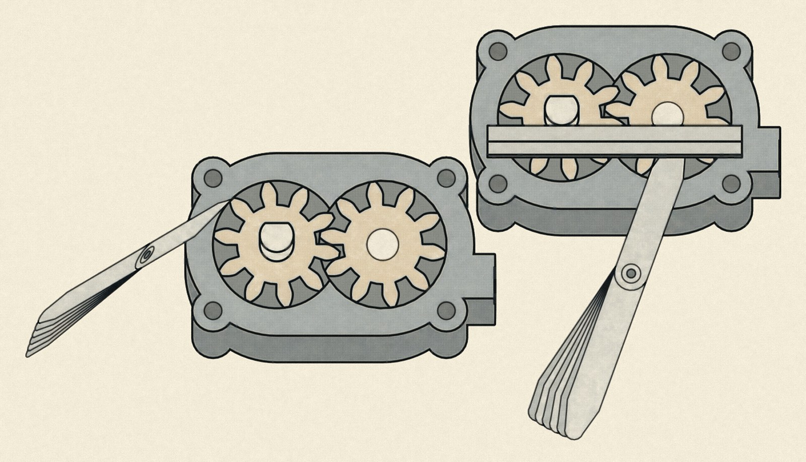
Left the circumferential clearance between gear and housing wall, right the axial clearance with a straightedge across the housing face.
For practice, a simple consequence follows, which we sharpen further in the reconditioning article: if an engine is open anyway, the pump should either be measured or replaced. "Looked fine" is not an inspection for a component whose wear plays out in hundredths of a millimetre — it's a hope.
¶ Our conversion in cross-section
Which brings us to the component this is really all about. Our conversion kit 1009790 replaces the entire balancer shaft module in the EA189, including its tightly sized Duocentric pump and wearing hexagon drive, with a standalone oil pump without a balancer shaft module, featuring a robust drive and, depending on choice, roughly 35 or roughly 116 percent more delivery rate. Everything this article has established up to this point is built into this design: the increased delivery rate raises the weak lower end of the curve, the standard pressure relief valve caps it at the top as ever, and eliminating the drive-dog weak point removes the most common drive failure path at the same time.

Which of the two pump stages is right for your engine, and why we consider this decision more important than any other detail of the order, is covered in the companion article Why more delivery rate is always the better choice. And for anyone wanting to go deeper still: the most fascinating details of this pump are precisely the ones we don't publish — the exact design of the delivery mechanism, the curves measured against defined reference conditions, the findings from our teardowns of used modules. This data has taken years to build up and remains at the core of our edge. What we can make public, you've just read.
¶ See also
- Why more delivery rate is always the better choice
- The balancer shaft module in the 2.0 TDI (EA189)
- Oil pressure isn't just oil pressure: measurement position
- Why we don't promise bar values
- Every engine is a one-off: manufacturing tolerances
- Timing belt in oil: the time bomb you can't inspect
Transparency note: we develop and sell conversion kits for the engines described here. The general technical information (designs, valve function, clearance values, test standards) comes from technical and workshop literature and is marked in the text as orders of magnitude; the hot-idle measurement values come from our own measurement practice.