¶ Oil Pressure Measuring Point: Why One Reading Deceives
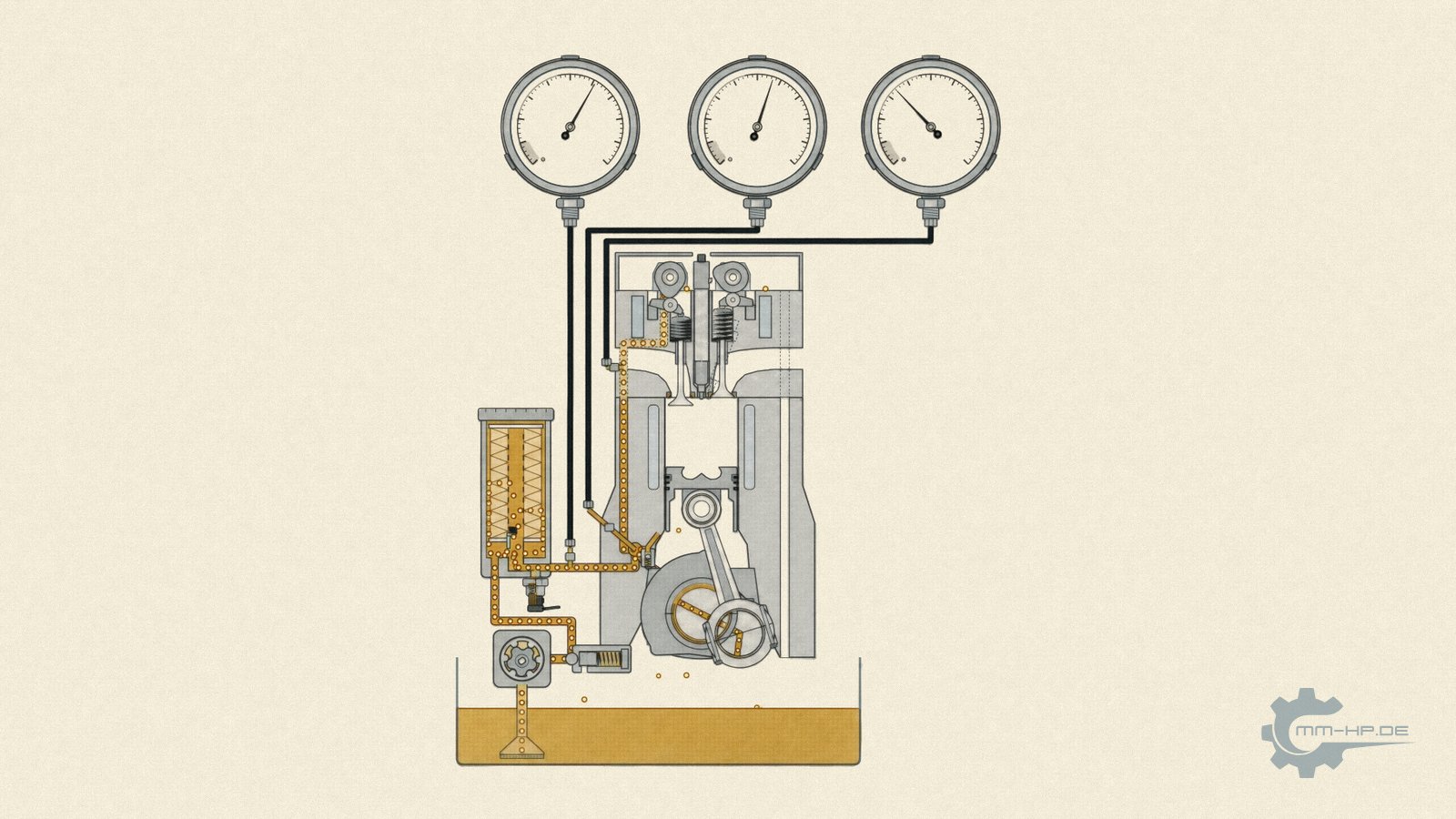
Schematic. The animation is further down in this article.
¶ The key points at a glance
"My engine has 3 bar of oil pressure." That sentence sounds precise and says almost nothing as long as one piece of information is missing: WHERE it was measured. Oil pressure is not a property of the engine that you can tap off at any convenient point, the way you would read the voltage of a battery. It is the result of a flow moving through a long chain of resistances, and it drops in stages along that chain. Right behind the pump the value is highest, in the main oil gallery it is already lower, and at the big-end (conrod) bearing, according to documented practical examples, only about half of the main-gallery pressure actually arrives. A single measurement point therefore never describes "the engine's oil pressure" — only the condition at that one specific location.
On top of that comes a sensitivity that hardly anyone has on their radar: oil flow through a bearing clearance grows with the third power of the clearance height. A difference of only a few thousandths of a millimetre, whether from wear or from normal manufacturing tolerances, shifts the pressure balance throughout the entire circuit. And depending on the fault pattern, the very same defect produces completely different symptoms at different measurement points: a worn bearing lowers pressure downstream, while a blocked spray nozzle actually backs pressure UP upstream — the gauge then reports excellent readings while the piston beneath it is starving.
This is exactly why, in our development work, we measure at several positions simultaneously, right into the supply passages of the bearing gallery, and exactly why you should treat forum comparison values that omit the measurement point for what they are: numbers with no address.
So much for the short version. The long version takes you on the journey of a drop of oil through the engine, station by station, with the pressures, valves and clearances along the way, and explains why, in the end, it is precisely the most important locations that are supplied worst of all.
¶ A sentence that sounds precise and says nothing
In forums and workshop conversations, oil pressure values are traded like fixed stars: "Mine has to be 2 bar when warm." "Mine still had 1.4." "Below 0.9 it gets critical." Ask WHERE these values were measured and the room goes quiet, or you get a grab-bag of answers: sometimes at the removed oil-pressure switch, sometimes at the oil filter flange, sometimes at an adapter fitted in the cylinder head. The numbers still get cheerfully compared with each other, as if they described the same thing.
They do not, and the reason is not a technicality but basic physics. Once you understand it, you read every oil-pressure discussion with different eyes, and you always ask the same question first: where was the sensor sitting?
¶ Oil pressure is a resistance, not a property of the pump
Let's start with the most widespread misunderstanding: "the pump makes the pressure." A positive-displacement pump, of the kind that works in an engine, does not initially generate pressure at all — it generates a flow rate. It pushes a fixed volume of oil into the gallery system per revolution, stubbornly and regardless of what happens downstream. Pressure only arises because this oil runs up against resistances: narrow bores, deflections, filters, bearing clearances, nozzles.
The garden hose picture captures it well: open end, plenty of flow, hardly any pressure. Put your thumb over it and the pressure rises, because the resistance rises — not because the pump has become stronger. The reading at any given point in the oil circuit is therefore always a statement about BOTH: what the pump is delivering, AND everything downstream in the way of resistances and outflows. If a clearance changes somewhere at the back, the display at the front changes too. For this reason alone, a single point can never describe the system.
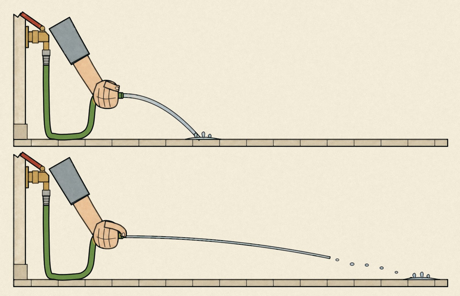
Same tap, same opening. The thumb raises the resistance, which is why the pressure rises, not because the tap delivers more.
¶ The journey of a drop of oil
Let's follow the oil on its way, station by station, because at each one it loses some of its pressure, and each one tells a story about the design.
Station 1, the pump. Here the journey begins at the highest pressure in the system. Right at the outlet, the pressure relief valve (PRV) stands guard: with cold, viscous oil, the resistance of the circuit would otherwise produce dangerous spikes, so the valve opens and lets excess oil return to the sump. As a rough workshop rule of thumb, a minimum of around 2 bar circulates for normal operation at running temperature — a rule of thumb, mind you, not a factory value, and strongly engine-dependent. It refers to driving, not idling: at hot idle even a healthy engine often sits below 1 bar, in the range where a workshop gauge no longer guarantees any accuracy.
Station 2, the oil filter. It, too, is a resistance, and it has a back door you need to know about: the filter bypass valve. If the filter is clogged or the oil is too viscous in winter, this valve opens and lets the oil pass UNFILTERED — lubrication takes priority over cleanliness. A clever safeguard with a dark side, because in bypass operation, particles travel unhindered into the entire circuit, which is what turns this unassuming valve, combined with abrasive debris in the oil, into a serious matter.
Station 3, the main oil gallery. The central distribution line in the block; from here, supply branches off to the bearings, cylinder head and nozzles. This is the standard measurement point in the technical literature — if a serious measurement is taken at all, it is taken here, BEFORE the bearings. Remember this address; it will matter again shortly.
Station 4, the crankshaft main bearings. They are typically fed with a supply pressure of roughly 2 to 5 bar. And here something fascinating happens that is regularly missing from the oil-pressure discussion: the bearing generates its own load-bearing pressure. The rotating shaft draws the oil into a wedge-shaped clearance and builds up hydrodynamic pressures there that are a multiple of the pump pressure — this is the only way a plain bearing can carry a load without contact at all. The pump's supply pressure has a more modest but vital job here: delivering enough oil to keep that wedge from ever collapsing. At this point, oil pressure is quite literally supply-chain logistics.
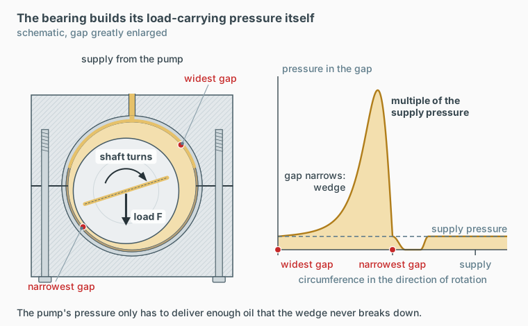
Schematic, gap greatly enlarged. The rotating shaft builds the load-carrying pressure in the wedge-shaped gap itself, the supply only replenishes the oil.
Station 5, the big-end (conrod) bearings. The most difficult customers in the system. They sit on a rotating crankshaft, and the oil reaches them through bores in the shaft itself, against centrifugal forces that grow with the square of rotational speed. Practical literature documents the cost of this journey: of roughly 4 bar in the main oil gallery, only about 2 bar remains by the time it reaches the big-end bearing — half of it lost to flow resistance and physics. The most important, most heavily loaded bearing in the engine ends up at the back of the queue.
Station 6, camshaft bearings and valve train. Further up, further away, even less residual pressure, but also less load.
Station 7, the piston-cooling spray nozzles. They cool the piston crowns with oil jets and are, by design, major consumers — this is one of the reasons modern diesel engines need more powerful pumps. Their check valves only open above a minimum pressure, so that the bearing supply isn't tapped at idle. After that, the oil flows back to the sump without pressure, and the journey begins again from the start.

The journey of a drop of oil from cold start to warm. The numbers match the stations in the text. The ladder on the right shows how the pressure falls from station to station; the three gauges at the filter flange, main gallery and cylinder head show three different readings at the same moment. When cold, the pressure relief valve and the bypass valve are open; when warm they are closed, and the spray nozzle closes at warm idle.
The lesson from this journey in one sentence: there is no single pressure in this system, there is a pressure GRADIENT, and every measurement point sits at a different height on that gradient.
¶ The cube rule: why thousandths of a millimetre control the gradient
How steep the gradient turns out to be is determined by the outflows along the way, above all the bearing clearances. And their physics has real teeth: according to lubrication theory, leakage flow through a bearing clearance grows with the THIRD power of the clearance height. A bearing with double the clearance does not release twice as much oil — it releases, by calculation, eight times as much.
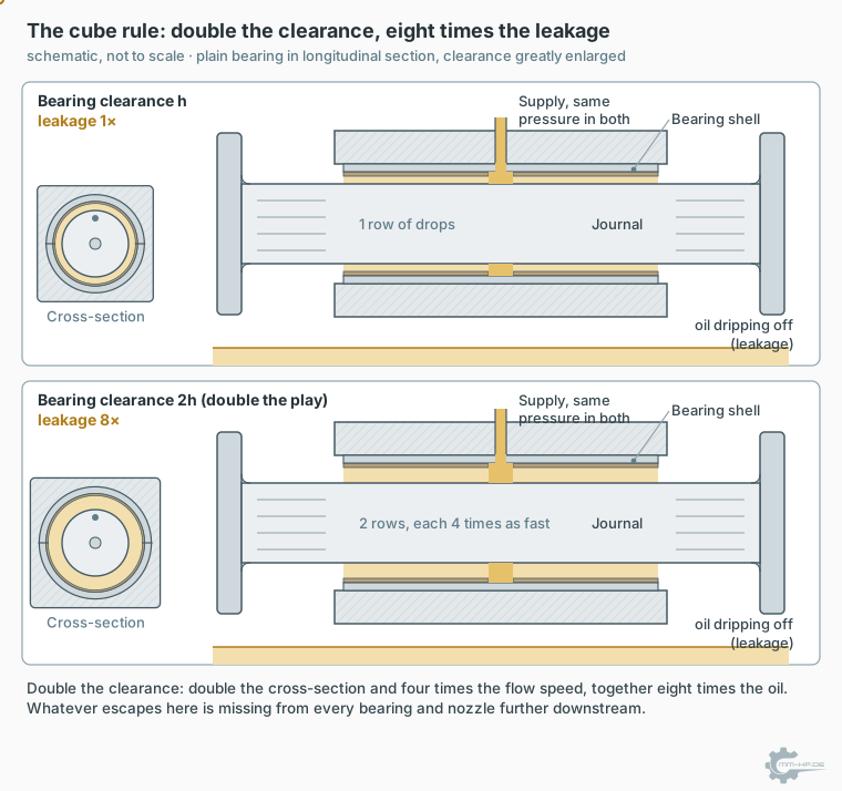
Double the clearance, eight times the leakage: double the cross-section and four times the flow speed together make eight times as much. Clearance drawn greatly enlarged.
Rule of thumb: with bearing clearance, the height cubed is what counts. What sounds like caliper folklore in fact decides the pressure gradient of the entire engine.
This cube rule has two practical faces. The first is wear: growing bearing clearances lower the pressure for everything downstream, gradually and for a long time unnoticed, because the usual measurement points sit far upstream. The second is scatter: even brand-new engines differ in their clearances by micrometres, entirely within specification, and thanks to the third power, their pressure gradient is therefore measurably individual. On top of that comes the surface finish of the passages themselves, whose roughness also determines flow resistance — likewise a product of manufacturing. It is therefore no use reading a decent value at a convenient point if a small, much more important passage further along is supplied completely differently.
¶ Three more laws from the oil passage's physics textbook
The cube rule for clearances has three siblings that also govern the pressure gradient in the engine, and all three work in the same direction: they make oil pressure a deeply local and deeply individual quantity.
First, the passages themselves. Flow through round channels is governed by the Hagen-Poiseuille law, and its core message is even more drastic than the cube rule: flow rate depends on the FOURTH power of the radius. A passage with half the diameter does not deliver half the flow — it delivers a sixteenth, equivalent to sixteen times the resistance. This is why the fine supply bores at the end of the chain are so sensitive to anything that narrows their cross-section even slightly, from manufacturing tolerances to deposits from contaminated oil.
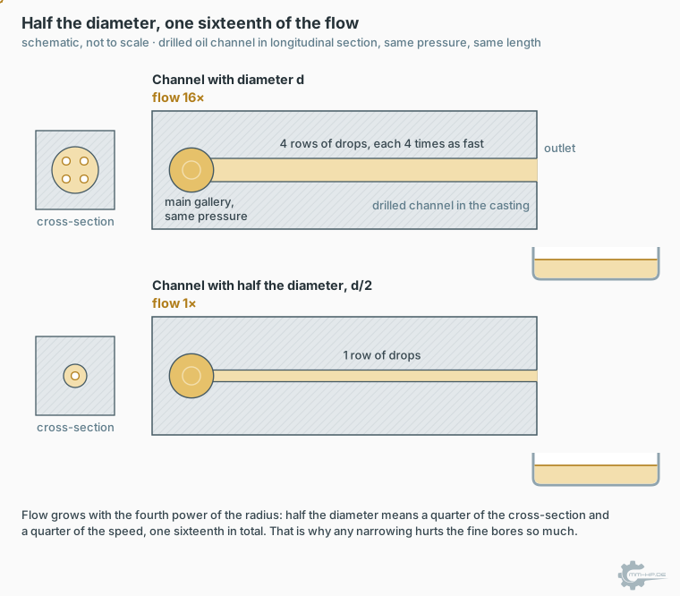
Half the diameter: a quarter of the cross-section and a quarter of the speed, one sixteenth of the flow in total. Schematic.
Second, the branches. In addition to friction along the passage wall, every branch, every deflection and every change in cross-section adds further, localised pressure losses; fluid dynamics captures these through separate resistance coefficients for each disturbance point. From the oil's point of view, an engine block is a course made up of dozens of such disturbance points, and each one costs a share of pressure, on top of pure passage friction. Even without any wear at all, it is therefore physically inevitable that a measurement point located behind five branches reads lower than one located behind just one.
Third, temperature, with a number worth remembering. Everyone knows that warm oil is thinner. Few people know just HOW dominant this effect is: the viscosity of oil falls exponentially with temperature, described by the Vogel equation of lubricant technology, and the technical literature offers an impressive point of comparison: a single degree of temperature change shifts viscosity by roughly as much as a pressure change of around 300 bar. Put differently: worlds lie between a measurement taken at 80 degrees and one taken at 95 degrees oil temperature — and at every measurement point simultaneously. Anyone comparing oil pressure values without a temperature reading is, in reality, comparing temperatures; the full scope of this problem fills an article of its own.
¶ The same defect, three different readings
Now it gets diagnostically interesting, because the cascade logic implies: where a fault sits determines what a gauge shows and where. Three textbook examples:
The worn bearing. Excessive clearance, cube rule, increased outflow: pressure drops, but above all DOWNSTREAM of the leak and at weak points beyond it. A measurement point far upstream at the filter flange may meanwhile still show reassuring values.
The blocked spray nozzle. One consumer drops out, the oil backs up: pressure upstream actually RISES. The gauge reports excellent readings while the piston beneath the dead nozzle quietly overheats. A "good" reading can therefore literally be a symptom of damage.
The slowly failing pump drive. Brief pressure dips during load changes, millisecond events that a damped needle gauge inherently swallows, at every position.
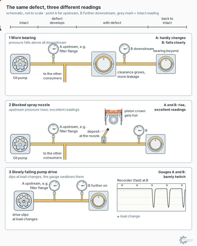
Same engine, three faults, three different readings. Grey marks show the intact reading. A worn bearing mainly depresses the pressure behind it, a blocked nozzle makes the gauges report excellent readings, and only a fast recorder sees the brief dips of a slipping drive.
Anyone measuring at only one point simply cannot distinguish between these cases. They have a number, but no diagnosis.
¶ Why forum comparisons multiply apples by oranges
With this in mind, it's worth taking a second look at the forum wisdom quoted at the start. What gets compared there is typically: measurements at different POSITIONS (switch port, cylinder head, filter flange, wherever the adapter happened to fit), with different DEVICES of unknown quality, at different and mostly unknown OIL TEMPERATURES, on different ENGINES with individual manufacturing scatter. Any single one of these variables is enough to break comparability; together they are hopeless. Publicly available, verified factory target-value tables by rpm and temperature essentially do not exist for these engines, incidentally — the numbers in circulation are almost without exception individual measurements taken by laypeople, passed along until they harden into perceived truth.
And the standard-fit oil-pressure switch? It sits at ONE location, depending on the engine on the oil filter housing, early in the circuit, or on the cylinder head, right at the end, and knows exactly one threshold. It is the last line of alarm, not a measuring instrument and certainly not an early-warning system. Whatever happens elsewhere in the system simply does not exist for it: fitted at the filter, it cannot see how much pressure is still left beyond the bearings.
¶ The consequence: measure at multiple points, or don't judge at all
All of this leads to the working method we use when approaching these engines: we take oil pressure readings at several, deliberately chosen positions SIMULTANEOUSLY, from the pump all the way into the supply passages of the bearing gallery, time-synchronised with rpm and oil temperature, at millisecond resolution. Only this picture shows the gradient instead of a single point on it, and only with it can the fault patterns described above be told apart. How this measurement technology is built, why nothing like it existed to buy, and how we derive our internal metric, the VHFI (Volumetric-Hydrodynamic Feed-Pressure Index), from the relationship between delivery volume and pressure distribution, is covered in the linked articles.
The choice of measurement positions itself is a piece of development work we don't disclose in detail: where it makes sense to measure in these engines without distorting the system is knowledge that has grown out of years of teardown and measurement work, and we ask for your understanding that we protect it. Even so, you can put the underlying lesson to use every day: whenever you come across an oil pressure figure, ask first for its address. Most of the time, that alone settles the discussion.
¶ See also
- Why off-the-shelf oil pressure gauges don't deliver reliable readings
- Why measurements taken before and after a conversion cannot be compared
- Every engine is a one-off: manufacturing tolerances and oil pressure
- How we measure oil pressure: our own hardware, our own software
- The oil-pressure warning light: what it really tells you and what it doesn't
Transparency note: MMHP has been developing, testing and manufacturing its own products for the automotive industry for over 25 years, including solutions for the oil supply of VW TDI engines. The fluid-dynamics and lubrication fundamentals of this article are documented with sources in our reference dossier; rules of thumb are marked as such.